- Network
- Best Practices
- Understanding Of Serial Ports
- Steps in RIP
- 4.1Build Network Topology
- 4.2 Assign IP address for the PCs
- 4.3 Assign fa0/0 address for the Routers
- 4.4 Assign Default Gateway for the PCs
- 4.5 Assign IP address for serial ports of Router0
- 4.6 Assign IP address for serial ports of Router1
- 4.7 Assign IP address for serial ports of Router2
- 4.8 Configure RIP
- 4.9 Simulate Working of RIP

This does help while assigning ip addresses to each port.
To navigate to preferences, either,
- click on Options and then Preferences
- Ctrl+R
Choose "Always Show Port Labels"


![]()
Note the Network Devices being used are
- Generic (Router-PT)
- Generic (PC-PT)


Accordig to the diagram,
- PC0 takes IP address: 10.0.0.2, Subnet Mask: 255.0.0.0 (represented by /8)
- PC1 takes IP address: 20.0.0.2, Subnet Mask: 255.0.0.0 (represented by /8)
Assign as below:
FOR PC0:

FOR PC1:

After assigning any IP address to any port or device, its best to label the port using the label icon present top
see best practices.
NOTE:
- Fast Ethernet 0/0 or Fa0/0 is the port in your router that connects to a PC.
- Hence we can set it up for both Router0 and Router1 connected to PC0 and PC1 respectively.
Type in below:

- First, type in
no/nto exit the configuration dialog. - Press the Enter key (Return).
- Type in
en(short) orenable(full). - Enter global configuration mode by typing:
conf t(short)configure terminal(full)
- To set the IP address of
fa0/0(FastEthernet0/0), navigate to it by typing:int fa0/0(short)int FastEthernet0/0(full)
- Enter the IP address (
10.0.0.1) with subnet mask (255.0.0.0, represented by/8) by typing:ip add 10.0.0.1 255.0.0.0(short)ip address 10.0.0.1 255.0.0.0(full)
- Boot the port (change the state from down to up) using the command:
no shut(short)no shutdown(full)
- Type
exitto exit fa0/0.
That's it!
Do the same for router2 set for fa0/0, IP address as 20.0.0.0.1 with subnet mask, 255.0.0.0
Do the same for router2 set for fa0/0, IP address as 20.0.0.0.1 with subnet mask, 255.0.0.0

The default gateway in the PC is the IP address of the fa0/0 port of the router it's connected to. Therefore, for PC0 default gateway is 10.0.0.1 and for PC1 it's 20.0.0.1 Set Default gateway by clicking on: PC0>Desktop > IP Configuration > Default Gateway Do the same for PC1.
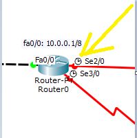
Note that each Router can connect to another Router, (int the case of Router-PT) via serial ports.
These serial ports are
- Serial 2/0
- Serial 3/0
By labelling the ports, you will now see the ports highlighted as Se2/0 (for Serial 2/0) and Se3/0 (for Serial 3/0). See best practices
These serial ports can either be DCE or DTE. - For DCE, It requires clock rate and bandwidth to be set.
- DTE, It doesnt require clock rate and bandwidth to be set.
To find out which of your ports are DCE and which is DTE, you can either: - On setting you preferences to label each port. DCE ports are labelled by a clock.
- Use a command, "show controller serial 2/0" (replace 2/0 by 3/0 for serial 3/0)
note: this command does not work in global configuration mode. So if you are in global configuration mode, get out of it by either using "exit" or Ctrl+C
For Router0, accrding to the [diagram](##network-topology-diagram)
I. its serial port, on the line connecting router0 and router2, has IP address: 192.168.1.254/30
To set IP address:
1. First check what kind of port this is. For me its a DCE serial 2/0. For you, instead of this it can be DCE serial 3/0, DTE serial 2/0 or DTE serial 3/0 . So properly note that before proceeding.
2. Since mine is a DCE serial 2/0, I do the following commands. Some commands are marked "Only for DCE". These commands need not be implemented for DTE.
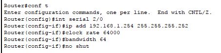
Type in::
Explanation::
[1] Enter global configuration mode by typing in "conf t" (short) or "configure terminal" (full)
[2] To set IP address of se2/0 (in my case) we navigate to it by typing,
"int serial 2/0"
if its se3/0 in your case, command: "int serial 3/0"
[3] Enter the IP address, that is 192.168.1.254 with subnet mask, 255.255.255.252 (which is represented by /30) By typing,
"ip add 192.168.1.254 255.255.255.252"
[4] [only for DCE] now you gotta set clock rate and bandwidth. We mostly use standard measurements bandwidth as 64 and clock rate as 64000 unless externally specified.
The commands are:
"clock rate 64000"
"bandwidth 64"
[5] Boot the port, that is change the state from down to up using command,
"no shut" (short)
"no shutdown" (full)
[6] Type in "exit" to get out of serial2/0 (in my case)
- its serial port, on the line connecting router0 and router1, has IP address: 192.168.1.249/30
In my case this port is DCE serial 3/0.
Type in commands:


For Router1, accrding to the diagram,
-
its serial port, on the line connecting router0 and router1, has IP address: 192.168.1.250/30
For me its a DTE serial 2/0 port, so I typed in commands

-
its serial port, on the line connecting router1 and router2, has IP address: 192.168.1.246/30
For me its a DTE serial 3/0 port, so I typed in commands


For Router2, accrding to the diagram,
- its serial port, on the line connecting router0 and router2, has IP address: 192.168.1.253/30
For me its a DTE serial 2/0 port, so I typed in commands

- its serial port, on the line connecting router1 and router2, has IP address: 192.168.1.245/30
For me its a DCE serial 3/0 port, so I typed in commands

- For this one should get into global configuration mode first, that's by "conf t"
- Then "router rip"
- Then add the respective networks for each router
Router 0:

Router1:

Router2:


The question arises in how we determine the networks for each of these routers. For this we will be doing and operations.
- We have fa0/0: 10.0.0.1 having subnet address of 255.0.0.0 we find the first network address by performing on an AND operation on the binary forms of 10.0.0.1 and 255.0.0.0, which gives ya 10.0.0.0
- Then we have se2/0: in my case its connected to 192.168.1.254/30 we find the network address by performing AND operation on binary forms of
- 192.168.1.254 and
- 255.255.255.252 (the subnet mask here is represented by 30, which in ip address form is 11111111.11111111. 11111111.11111100, which has a total of thirty 1s. convert this ip address to decimal and you will get 255.255.255.252)
- on performing and operation you get, 192.168.1.252
- Then we have se3/0: in my case its connected to 192.168.1.249/30 we find the network address by performing AND operation on binary forms of
- 192.168.1.249 and
- 255.255.255.252
- on performing and operation you get, 192.168.1.248
- Then we have se2/0: in my case its connected to 192.168.1.250/30 we find the network address by performing AND operation on binary forms of
- 192.168.1.250 and
- 255.255.255.252
- on performing and operation you get, 192.168.1.248
- Then we have se3/0: in my case its connected to 192.168.1.246/30 we find the network address by performing AND operation on binary forms of
- 192.168.1.246 and
- 255.255.255.252
- on performing and operation you get, 192.168.1.240
- We have fa0/0: 20.0.0.1 having subnet address of 255.0.0.0 we find the first network address by performing on an AND operation on the binary forms of 20.0.0.1 and 255.0.0.0, which gives ya 20.0.0.0
- Then we have se2/0: in my case its connected to 192.168.1.253/30 we find the network address by performing AND operation on binary forms of
- 192.168.1.253 and
- 255.255.255.252
- on performing and operation you get, 192.168.1.252
- Then we have se3/0: in my case its connected to 192.168.1.245/30 we find the network address by performing AND operation on binary forms of
- 192.168.1.245 and
- 255.255.255.252
- on performing and operation you get, 192.168.1.240
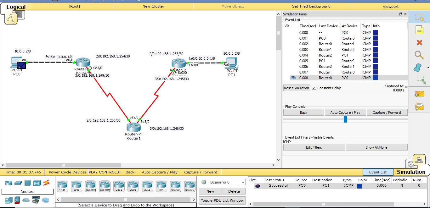
Basically, RIP protocol uses the path / route that has the least number of hops to get from the source to the destination. To get from PC0 to PC1, we have two routes:
Route1: PC0 <=> Router0 <=> Router2 <=> PC1
Route2: PC0 <=> Router0 <=> Router1 <=> Router2 <=> PC1
Route1 has lesser number of hops compared to Route2.
Hence when we simulate the packet transmission from PC0 to PC1, it should take Route1.
On removing Route1, RIP protocol chooses route2 to transmit packets from PC0 to PC1 since no other route exists
To simulate,enter Simulation Mode in the Bottom Right Corner (blue arrow).
Click the Envelope Icon and then click on PC0 and PC1 (red arrow)
In the Simulation Panel, Edit Filters, Click ICMP under IPv4
Then in play controls click capture forward to see the packet traverse route1.
at the end of it you should get an event list encircled in pink below and the successful status message highlighted by yellow arrow.

Now get rid of the connection line between router0 and router2.
Click the Envelope Icon and then click on PC0 and PC1
There is only one route in this case, that is route2, so the packets have no choice but to choose that route.
Normally packet simulation doesn't work the first time. So try doing it two times more.That is the same step of clicking the Envelope Icon and then click on PC0 and PC1.
If that doesn't work,check if you've entered the proper IP address for each device.
click on a device and then click Config and check each port address. Also check the gateways of the PCs.
On confirming correct port address, simulate once more.
if that fails again, test the working of the individual connection lines.
That is, Click the Envelope Icon and then click:
- PC0 and Router0
- PC1 and Router1
- Router0 and Router1
- Router0 and Router2
and so on and so forth.
if any of these connections fail, that means that there is an error in the 8th step,Configure RIP. If you have by mistake added a wrong network,make sure you are config mode and then after typing router rip you can type in this command to remove the wrong network is:
"no network 20.0.0.0"
where 20.0.0.0 can be understood as any wrong network.
Test again. it should work.
If you like this project, please consider starring ⭐ this repo on GitHub as it is the easiest and best way to support it.