 burble
How far could you take precision timing, a 555 and a healthy dose of ridiculousness ?
This project covers the creation of possibly the world's most accurate 555 timer (*) (**)
* for some definition of accurate, we'll measure it and see what this means
** because no-one else with any common sense would do this
Objectives
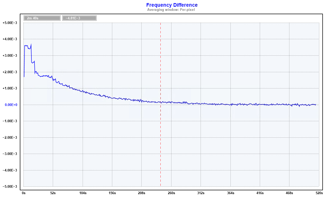
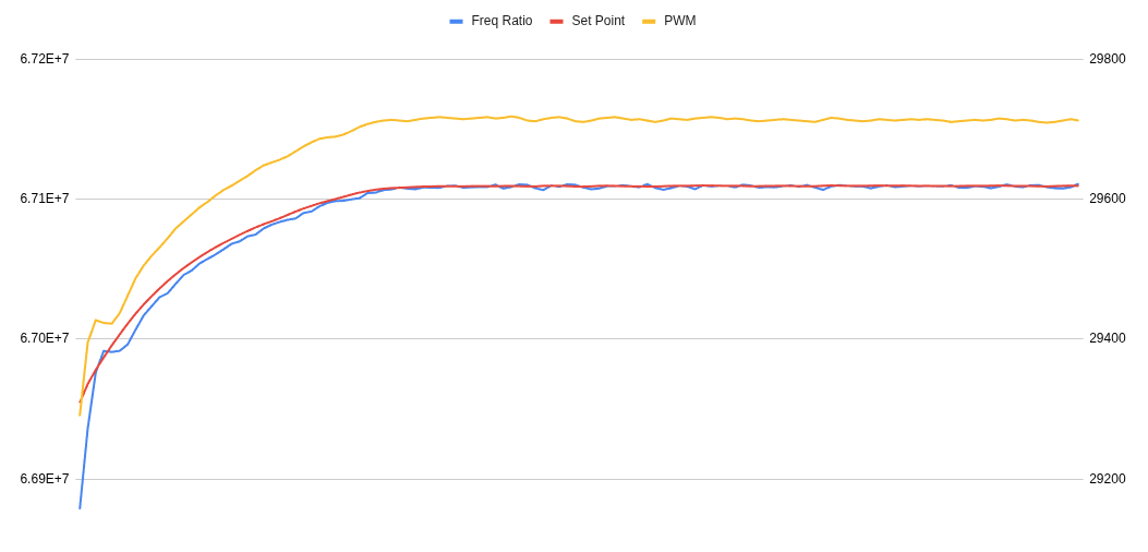
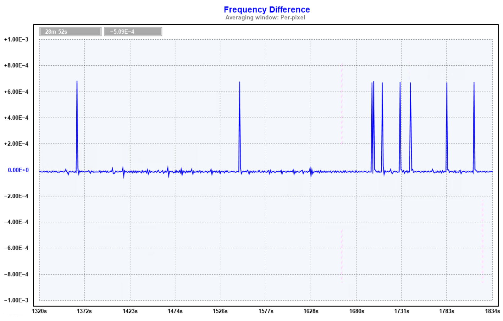
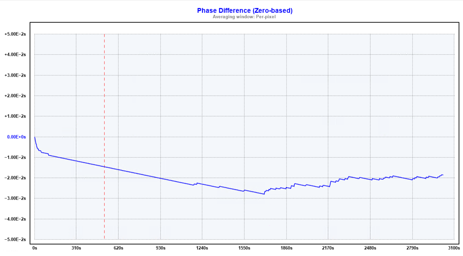
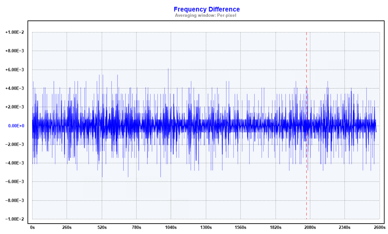
Lock a 555 timer to GPS and measure how well it performs.
Constraints
1) The 555 must output 1 PPS which is phase locked to GPS
Frequency locking won't cut it, one of the measures will be how well the 555 can track UTC.
2) No exotic oscillators or tricks
The project must use a normal astable 555 design with a standard RC oscillator. as commonly found in any textbook. No driving the 555 with a rubidium standard, or controller driven charging tricks.
3) No exotic components
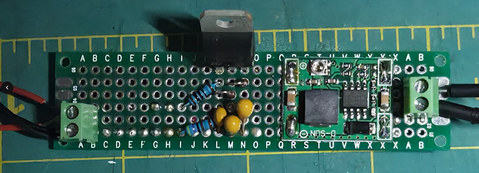
The project will be cheap and cheerful with parts I had to hand and without any specialist components. No special purpose ultra low noise regulators or op-amps; no expensive high precision capacitors or resistors.
High Level Design
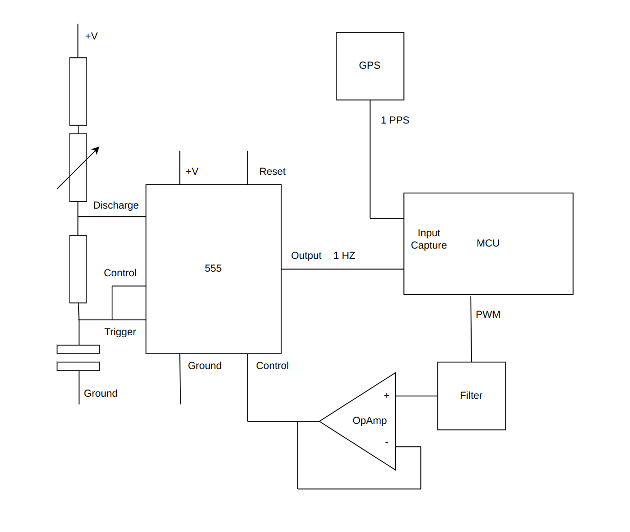
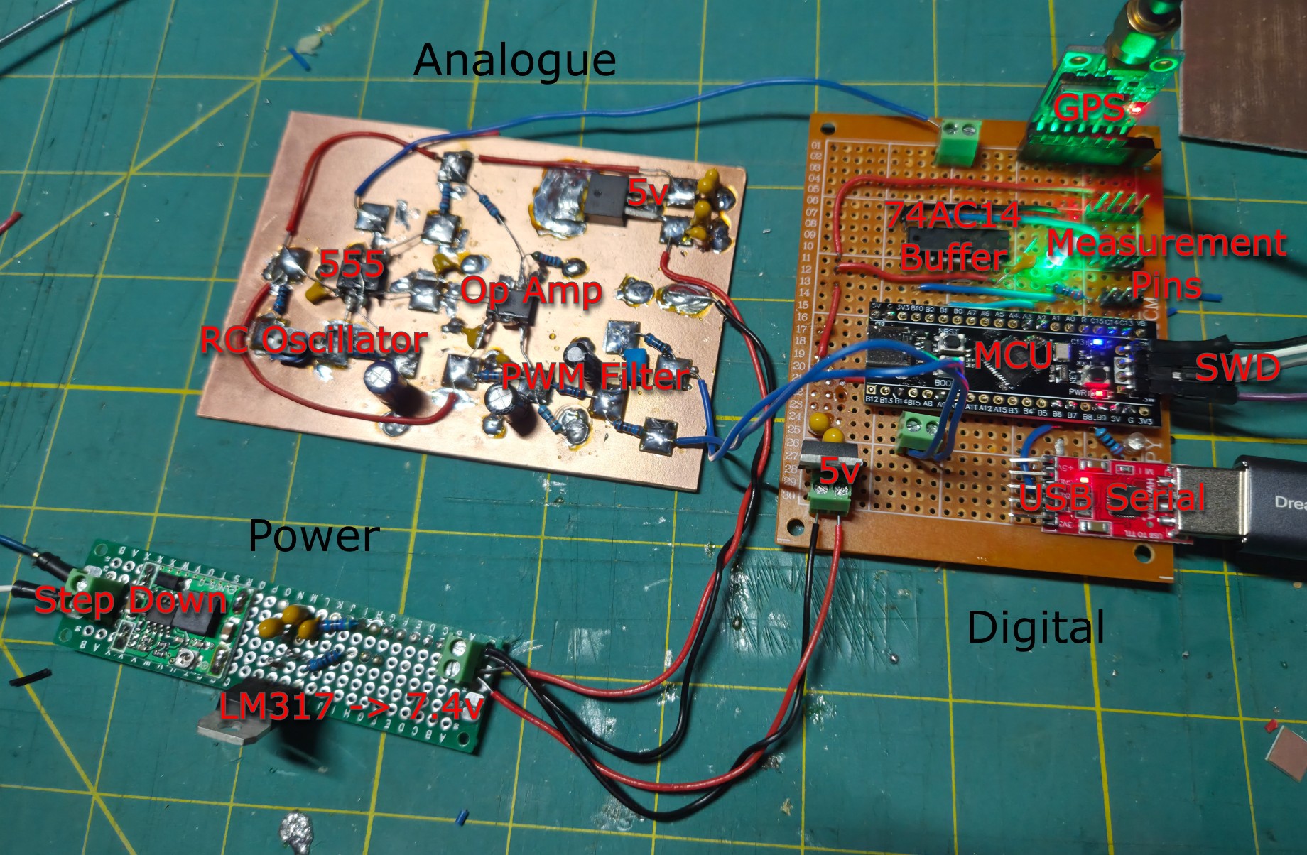
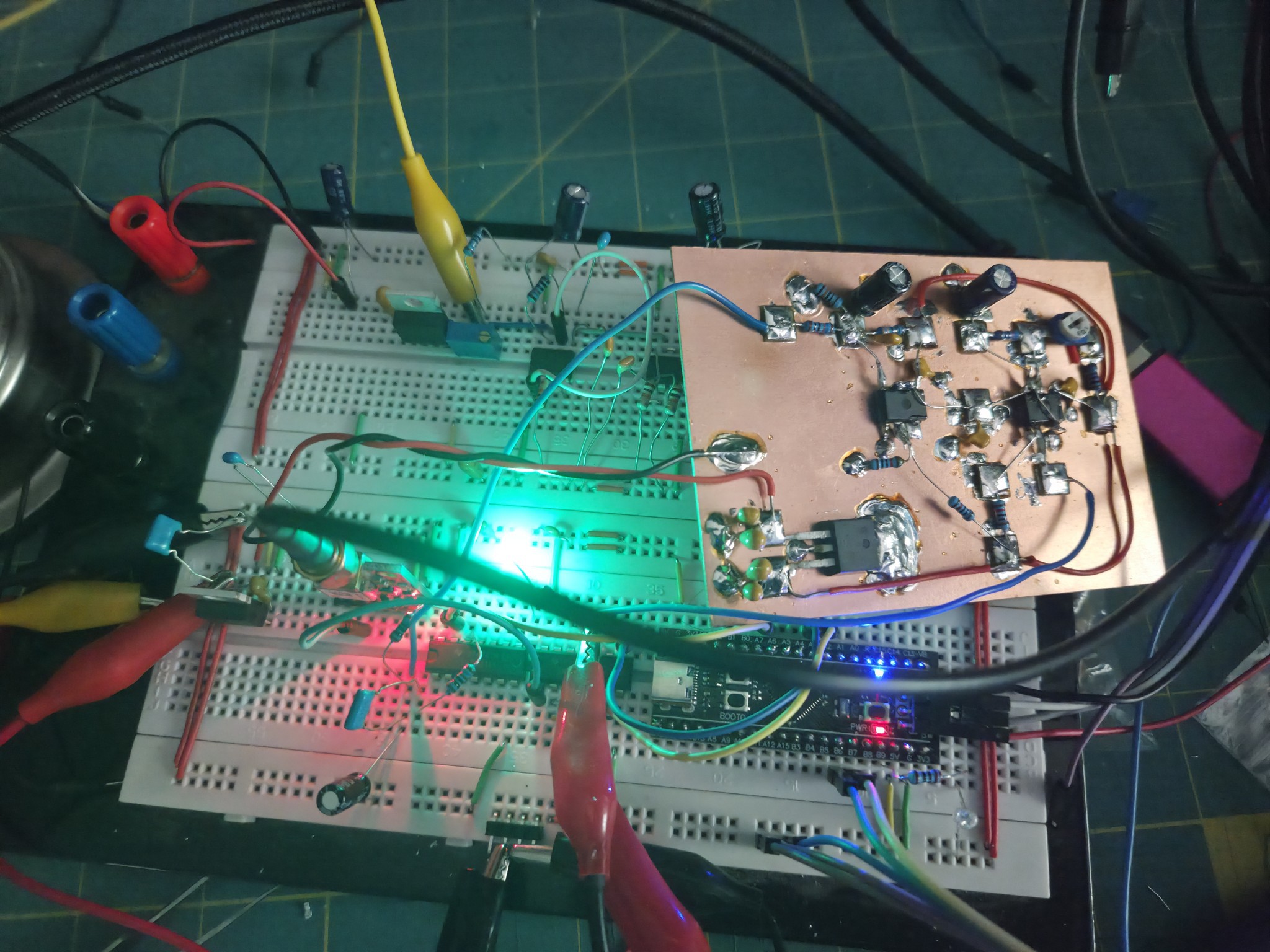
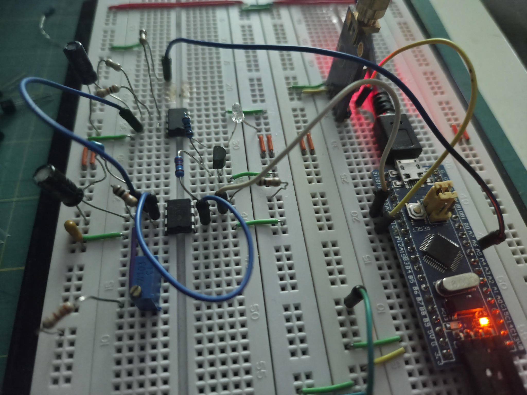
The basic oscillator design is fixed by constraint (2), we'll have a textbook astable 555 design with an RC oscillator, picking a capacitor and some resistors from the parts bin to get approximately 1hz. The only change here is to add a variable resistor so that the frequency can be roughly trimmed later on to centre the control loop voltages.
Whilst there are multiple ways that the frequency of the 555 can be dynamically adjusted, given constraint (2) the simplest approach is to manage the control voltage of the 555. Changing the control voltage changes the trigger thresholds of the 555 which allows the oscillation frequency to be varied as required.
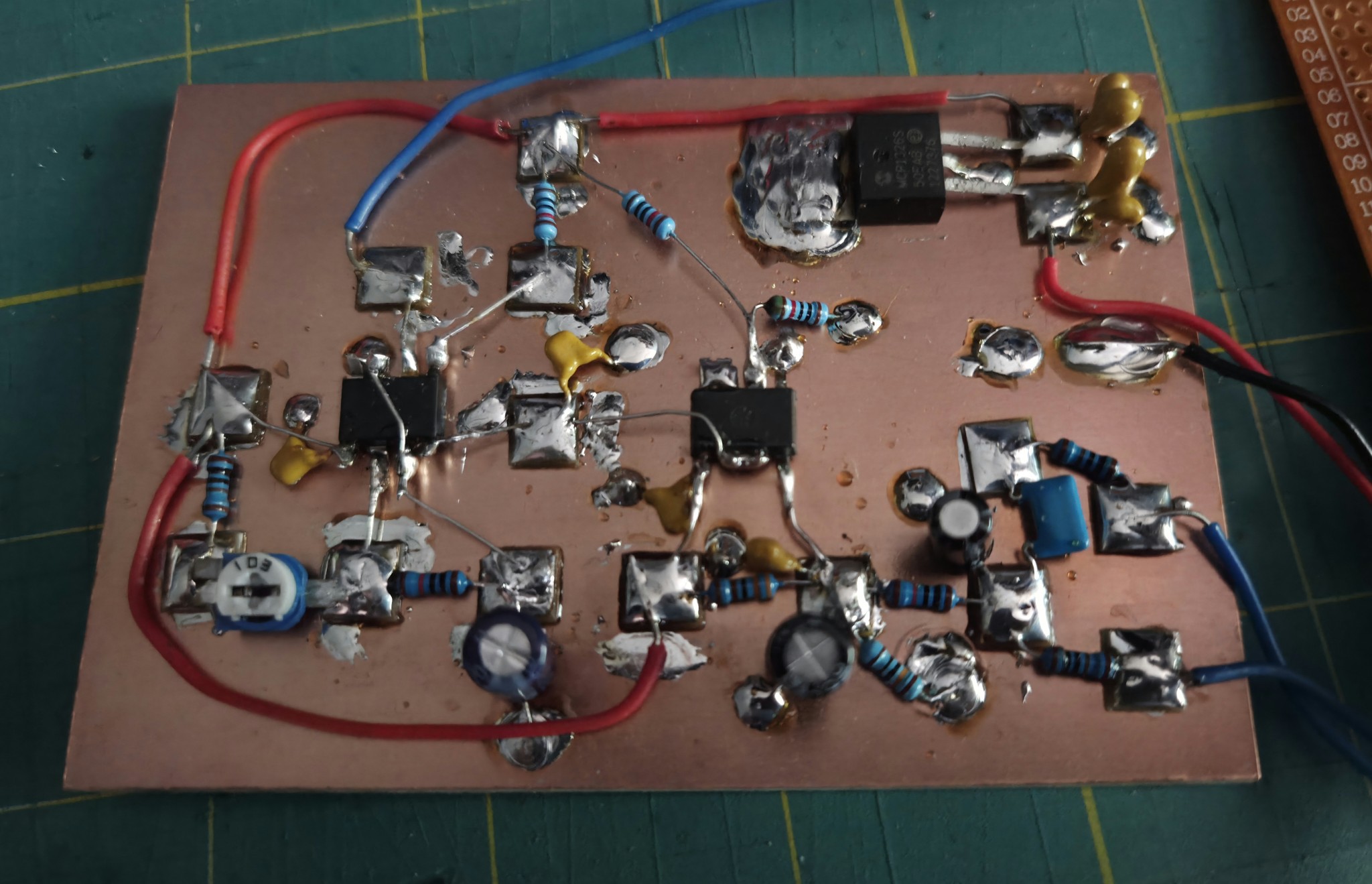
For the control loop, the only reasonable option is to use a microcontroller. Attempting to phase lock a 1 PPS with analogue components would be Hard and not practical given design constraint (3).
I chose to use the stm32 family, they are cheap and have decent clock speeds, but crucially have excellent timers with hardware capture support. After an initial proof of concept with an stm32f103 (blue pill), I switched to a stm32f411 (black pill) for a small frequency boost and 32-bit timer. A 32-bit timer simplifies the capture code considerably.
The job of the controller will be to capture the 1 PPS pulses from the 555 and GPS against its internal timer and then steer the 555 to match the frequency and phase of the GPS.
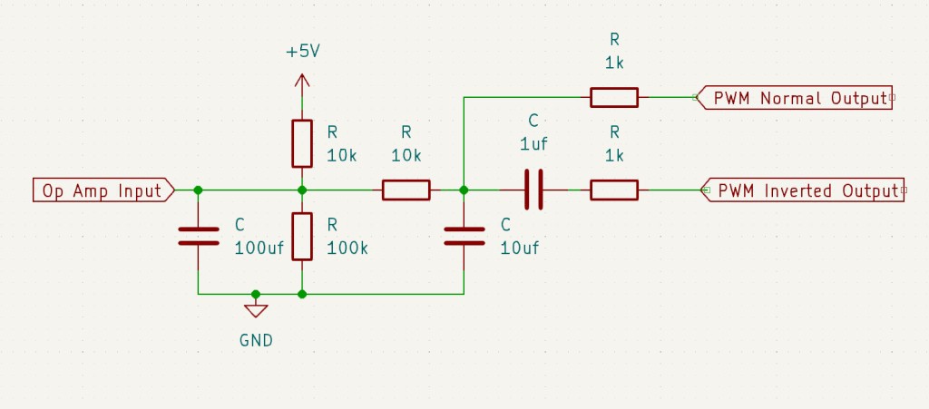
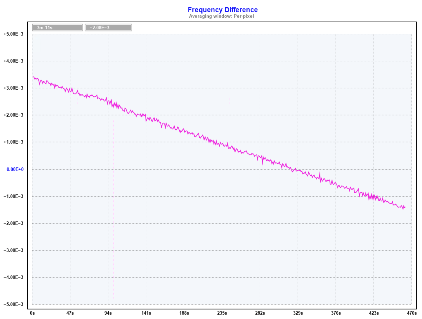
The software will use a dual PID to control the frequency and phase of the 555. The first PID manages the frequency and sets the steering output to achieve a set frequency. The second PID makes small adjustments to the frequency set point, drifting the phase forwards or backwards to achieve phase lock.
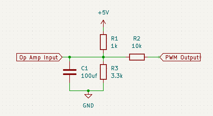
Steering of the 555 is achieved via a PWM DAC, output from the controller to the control pin of the 555 via an op-amp buffer. The control voltage precision will be in the uV range so care will be needed to effectively filter the PWM; the configuration of the filter will be found by experimentation and prototyping.


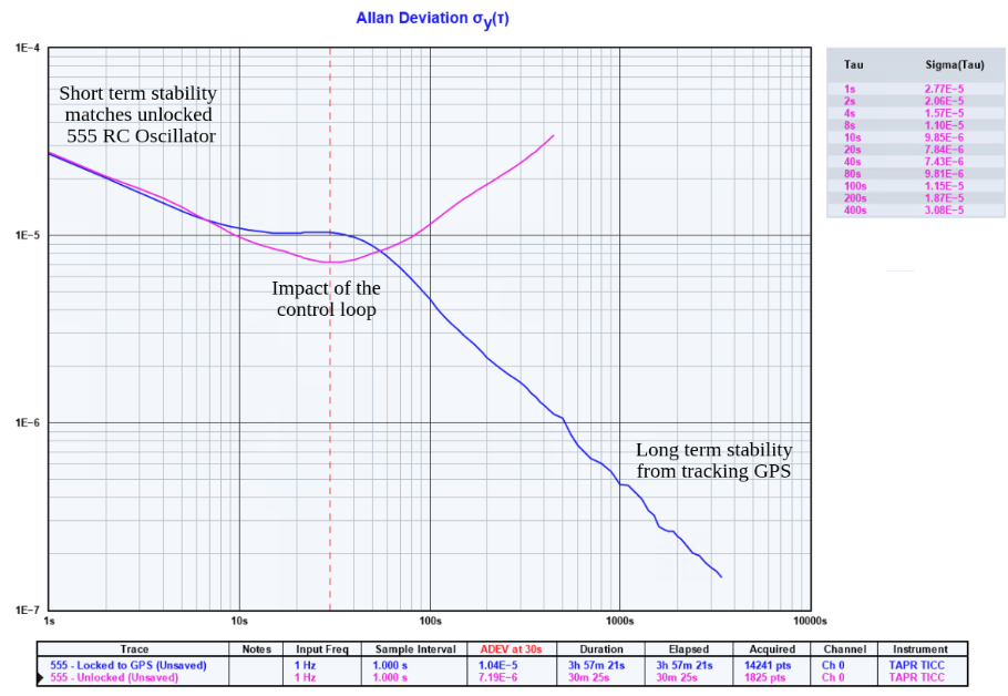

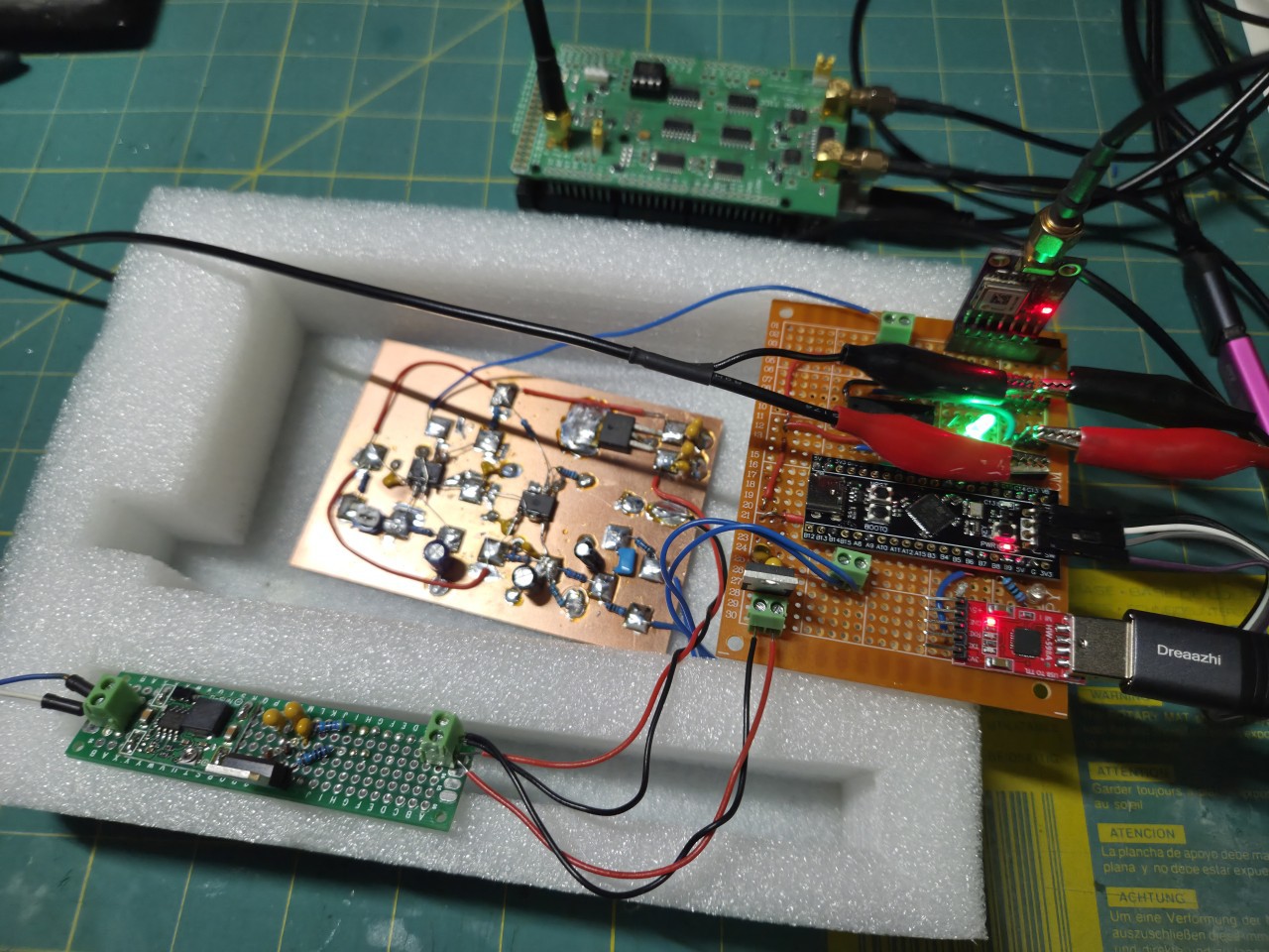


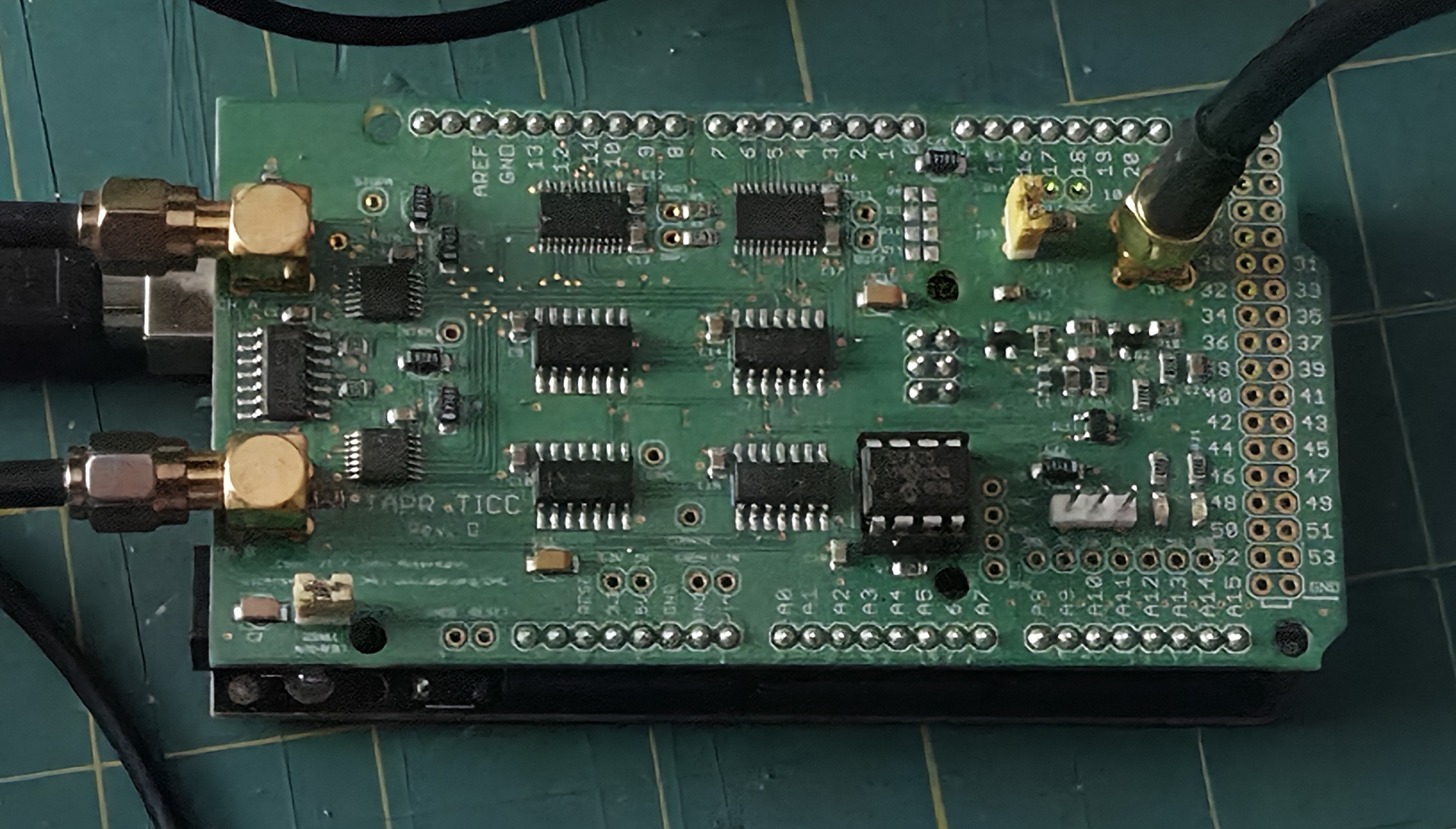
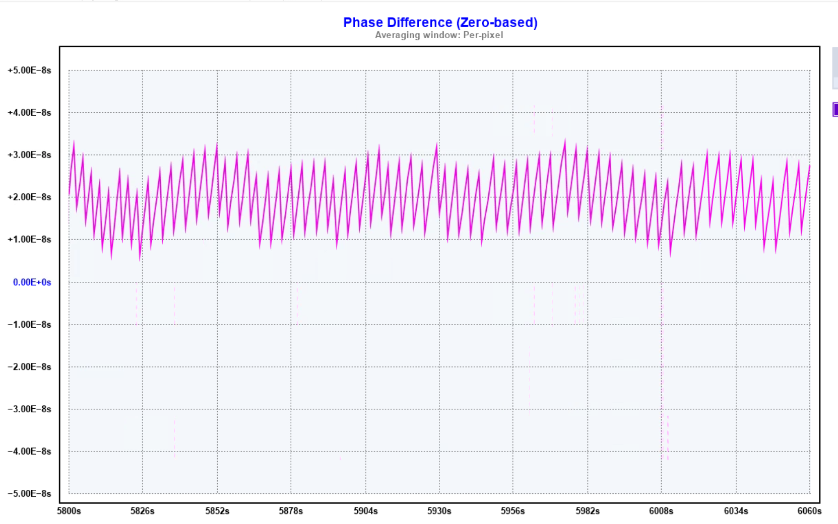 The TICC requires a 10mhz reference clock and has two timestamping channels. By using a GPSDO reference and providing the GPS PPS and 555 PPS on each channel a three cornered hat measurement can be performed to compare noise across the three sources.
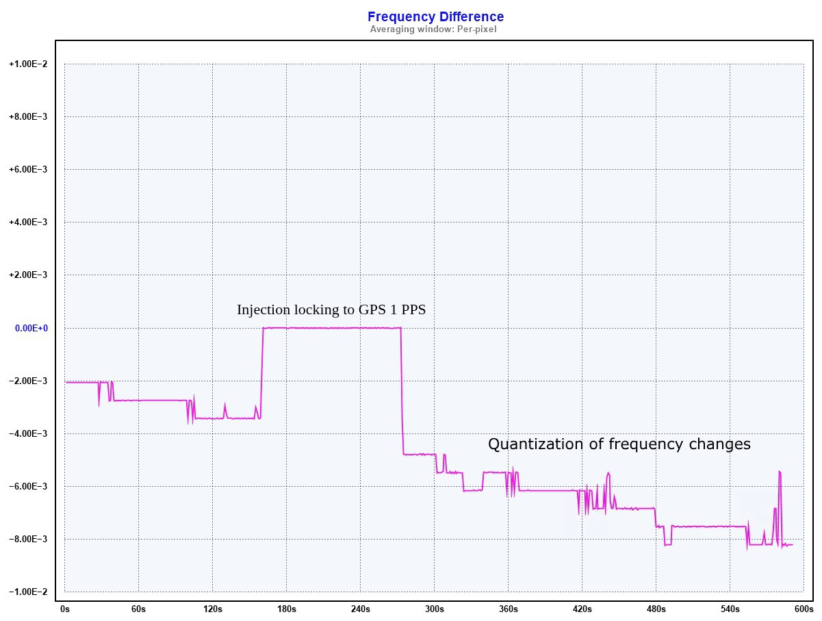
 Another Spoiler Alert from the Further Future
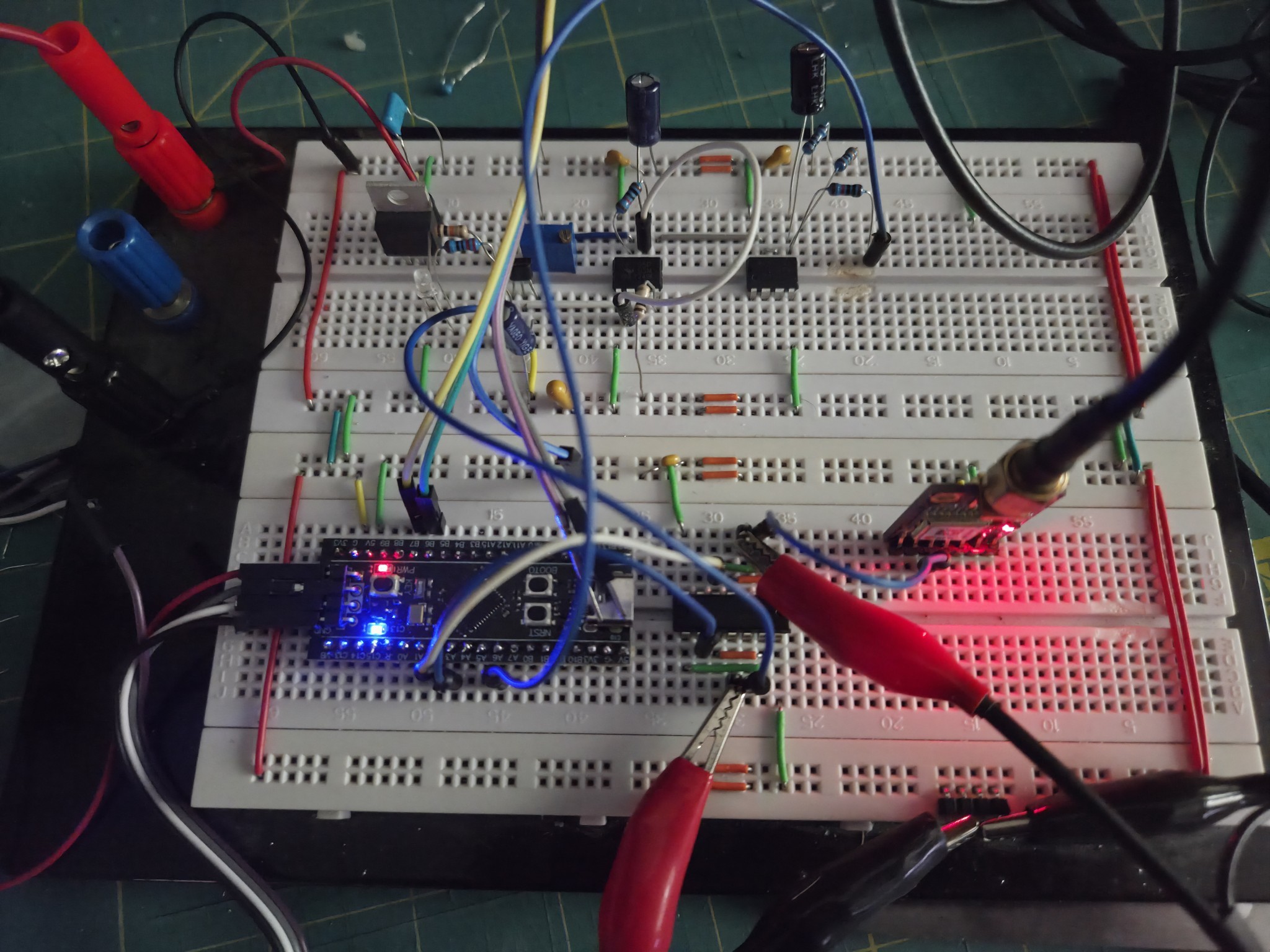


 gitmodimo

 Peter Walsh
 Rue Mohr